







Physics Ray Optics and Optical Instruments Diagrams for JEE Main and Advanced by PW
 Mehjabeen Hussain15 Sept, 2026
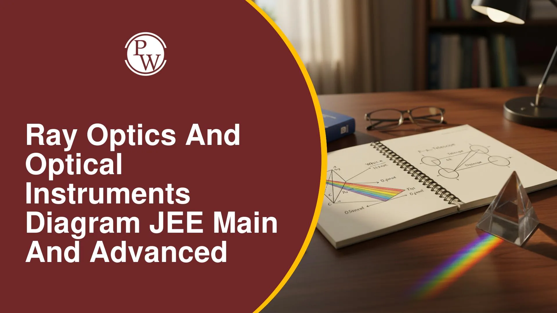
In Ray Optics, the path followed by a light ray determines how it is reflected, refracted, or used to form an image. Small changes in the object position, medium, surface, or optical arrangement can alter the resulting ray path, making diagram-based understanding particularly useful for this chapter.
For JEE Main and JEE Advanced, these diagrams can be referred to while studying image formation, refraction through different surfaces, mirror and lens arrangements, and the working of optical instruments. They can help you follow the movement of light from one optical element to another and relate the resulting ray pattern to the concept being tested.
Ray Optics and Optical Instruments Diagram PDF
The Ray Optics and Optical Instruments Diagram PDF by PW features visual references for key topics such as reflection, refraction, spherical mirrors, lenses, optical fibres, and optical instruments to support JEE Main and JEE Advanced preparation.
Ray Optics and Optical Instruments Diagram PDF
Why Use Ray Optics and Optical Instruments Diagrams for JEE?
Ray Optics requires you to follow the path of light carefully and identify how mirrors, lenses, and surfaces affect its direction. Diagrams can make these changes easier to track and connect with image formation concepts.
1. Trace Reflection of Light
Ray diagrams can help you follow the path of incident and reflected rays and identify the relationship between their directions and the reflecting surface.
2. Understand Refraction
Diagrams can show how light changes direction when it passes from one medium to another, helping you identify the incident and refracted rays.
3. Revise Spherical Mirror Ray Diagrams
Standard ray constructions for concave and convex mirrors can help you understand how the position and nature of an image depend on the object location.
4. Visualise Lens Image Formation
Lens diagrams can help you trace principal rays and determine the position, size, and nature of images formed by convex and concave lenses.
5. Understand Sign Conventions
Visualising the positions of objects, images, focal points, and optical centres can make the application of sign conventions easier while solving numerical problems.
6. Study Refraction Through Prisms
Prism diagrams can help you follow the deviation of light and understand the angles involved when a ray passes through a prism.
7. Understand Total Internal Reflection
Diagrams can illustrate the conditions for total internal reflection and make the relationship between the incident angle and critical angle easier to interpret.
8. Revise Optical Fibre
Visual representations of light travelling through an optical fibre can help you understand how total internal reflection enables light transmission.
9. Understand Optical Instruments
Diagrams of instruments such as microscopes and telescopes can help you identify their optical components and trace the formation of images through the system.
10. Interpret Ray-Based Questions
Accurate ray diagrams can help you identify the physical arrangement given in a question and determine which optical principle or equation needs to be applied.
These diagrams provide a visual reference for light paths, image formation, refraction, reflection, and optical instruments. They can make it easier to interpret ray-based problems and connect the given optical setup with the relevant concepts during JEE Main and JEE Advanced preparation.
You May Also Like :
FAQs
What are the important Ray Optics and Optical Instruments diagrams for JEE?
Why are ray diagrams important for JEE preparation?
What other JEE Physics resources does PW provide?









Get Free Counselling Today
and Clear up all your Doubts
 Live & recorded classes available at easeDashboard for progress trackingLakhs of practice questions