

Free Body Diagram: Importance, Procedure, Types

Free Body Diagram
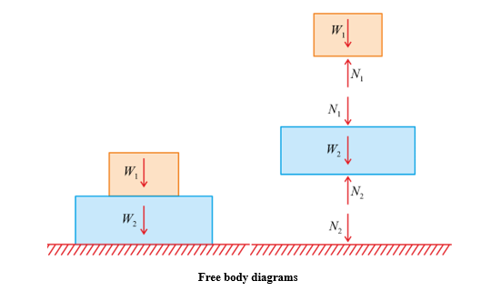
The process of solving problems in mechanics relies on the application of a few fundamental concepts and laws. Nevertheless, it is crucial to apply these laws carefully. To accomplish this, the initial step involves identifying all the forces acting on the specific body under consideration. In order to achieve accurate results, it is necessary to isolate the body from all other bodies and visually represent this isolation on paper.
“A Free body Diagram (FBD) is a sketch of the selected system consisting of a body, a part of a body, or a collection of interconnected bodies completely isolated from other bodies, showing the interaction of all other bodies by force.”
Importance of Free Body Diagrams
- Translates a physical problem into a mathematically analyzable form.
- Isolates a body or connected bodies from external forces for analysis.
- Represents both active (applied) forces and reactive (reaction) forces.
- Determines the type of force system acting on the body.
Procedure for Drawing Free Body Diagram
- Draw a neat and organized sketch of the entire structure or a selected part of it without supports, including relevant dimensions and angles.
- Indicate active forces with their magnitudes and directions at corresponding points of application.
- Show reactive forces resulting from each support.
- Apply the principle of transmissibility when convenient.
Note: We can assume any direction of reaction force (Upward or downward). If the calculated value of reaction is (+ve), the assumed direction is right otherwise wrong.
Types of Supports and their Reactions
The key step in mastering F.B.D. is determining support reactions. Structures like beams, trusses, frames, etc., have specific support arrangements. Different support types yield distinct reactions, which are classified as follows:
-
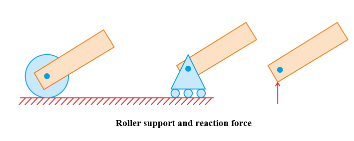
Roller Support:
A roller support is equivalent to a
frictionless surface
. The roller support possesses the ability to freely roll along the resting surface, but it restricts linear displacement in the normal direction. Consequently, it provides a reaction force in the normal direction to the supporting surface.
-
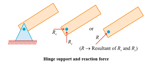
Hinge Support:
A hinge support is equivalent to a
friction surface
. The hinge support allows rotation but restricts linear movement at the pin end. As linear displacements are constrained horizontally and vertically, the reaction at the hinge support is resolved into two components: the horizontal reaction and the vertical reaction.
-
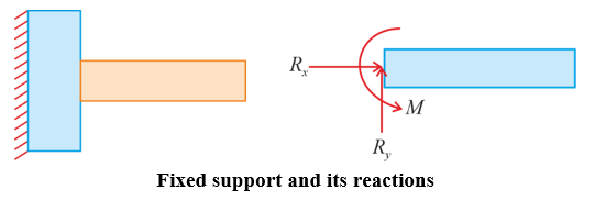
Fixed Support/ Built in Support:
When the end of a beam is fixed), it is referred to as a fixed beam. A rigid support restricts both linear displacement and rotation of the beam. Consequently, the components of reaction exerted at fixed end are the horizontal component R
x
, the vertical component R
y
, and the couple M.
FBD of some Example Problems
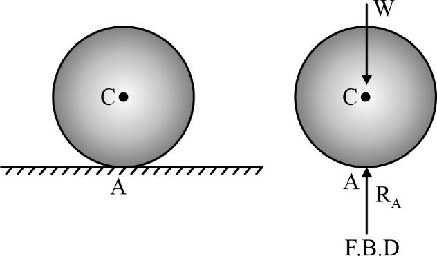
- FBD of ball resting on a horizontal surface.
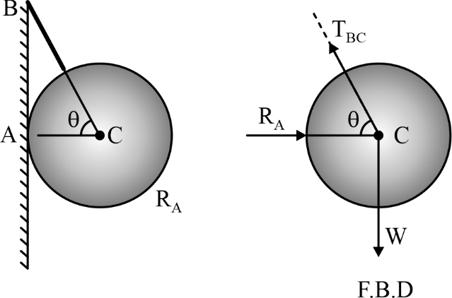
- FBD of ball hanging by a string and supported by a wall.
-
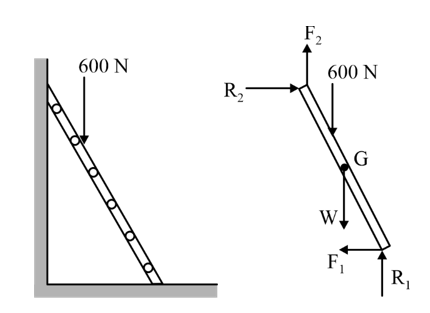
FBD of loaded ladder resting against a rough wall and rough floor.
-
FBD of two spheres in a container

-
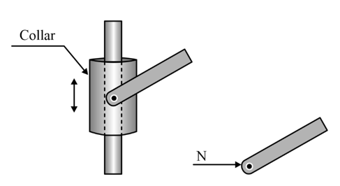
FBD of rod connected to free sliding guide
-
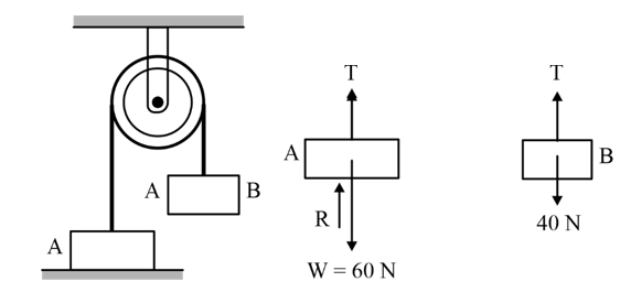
FBD of block in a rope and frictionless pulley arrangement
- FBD of rod supported by knife edge (fulcrum)