
Magnetic Field And Magnetic Field Lines
Magnetism of Class 10
MAGNETIC FIELD AND MAGNETIC FIELD LINES
All magnets have a space around them in which the force of attraction and repulsion can be detected. This space is known as magnetic field. We can describe the magnetic field around a magnet by magnetic field lines. These are the curved paths along which magnetic force is acting on them in the magnetic field of the bar magnet. These lines are called magnetic lines of forces.
MAGNETIC FIELD LINES:
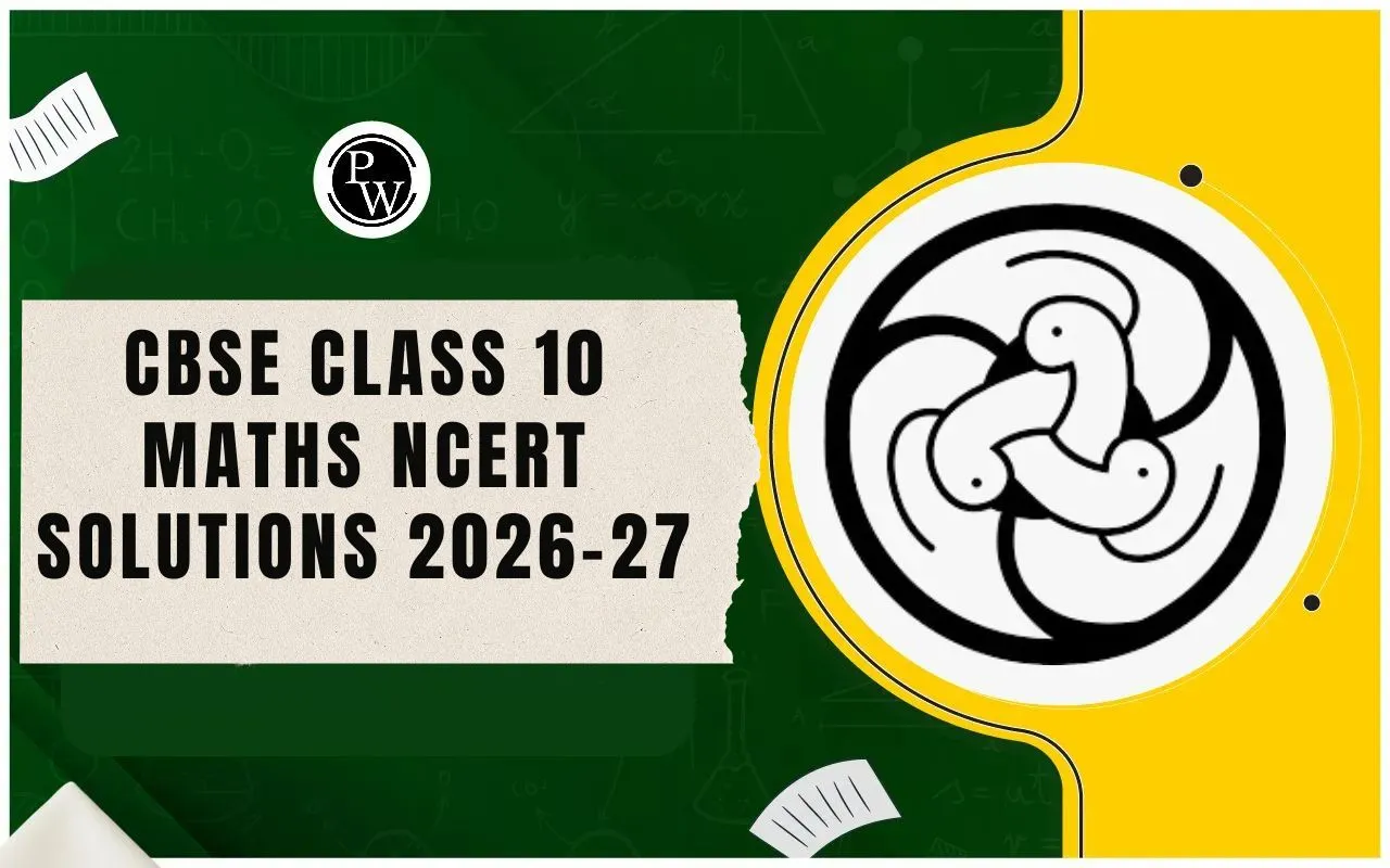
To know the magnetic lines of forces, place a magnet on a cardboard sheet and gently sprinkle some iron filings uniformly over it. The iron filings are found to arrange themselves in a pattern.
TRACING MAGNETIC FIELD LINES OF A BAR MAGNET USING A MAGNETIC COMPASS:
Take a paper sheet and fix it on a drawing board by pins. Place a bar magnet and mark its boundary. Now place a small compass needle close to South Pole of the magnet and mark two pencil dots at two ends of the needle. Now move the compass in such a manner that one end (N) of the needle coincides with the second pencil dot. Mark the position of the other end(s) with a dot. Repeat this process of moving the needle and marking dots at its two ends till its South Pole reaches the North Pole of the magnet. Get a smooth curve by joining the dots. This smooth curve represents a magnetic field line. By repeating the above process from the same pole of the magnet but different points, other magnetic field lines can be traced.
PROPERTIES OF MAGNETIC FIELD LINES:
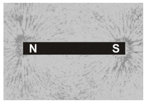
- A magnetic field line is a closed and continuous curve.
- A magnetic field line is directed from North Pole to South Pole outside the magnet. Whereas inside the magnet, the field lines are directed from south pole to north pole.
- The magnetic field lines are crowded near the pole where the magnetic field is strong and are far apart near the middle of the magnet and far from the magnet where the magnetic field is weak.
- The magnetic field lines never intersect each other because if they do so, these would be two directions of magnetic field at that point, which is not possible.
- In case the field lines are parallel and equidistant, these represent a uniform magnetic field. The Earth's magnetic field is uniform in a limited space.
MAGNETIC EFFECT OF CURRENT :
Hans Oersted, in 1820, first discovered that when an electric current is passed through a conducting wire, a magnetic field is produced around it. If a compass needle is kept in the vicinity of the current carrying wire, the needle is found to deflect in a definite direction. If the direction of current in the wire is reversed, then the direction of deflection of the needle is reversed.
AB is a wire lying in the north-south direction and connected to a battery through a rheostat and a tapping key. A compass needle is kept just below the wire. When the key is open i.e. no current is passed through the wire, the needle shows no deflection and points in the N-S direction (i.e. remains parallel to the wire) as shown in figure(a)
When the key is pressed and a current passes in the wire in the direction A to B (i.e. from south to north) and the north pole (N) of the needle deflects towards the west as figure(b). Thus, a current (or moving charge) produces a magnetic field. When the direction of current in the wire is reversed by reversing the terminals of the battery, the north pole of the needle deflects towards the east as figure(c).
AMPERE'S SWIMMING RULE:
Let the observer imagine himself to be swimming along the conductor in the direction of the current and facing the magnetic needle, then the North Pole of the needle will be deflected towards his left hand.
Magnetic Field due to a Straight Current Carrying Wire :
When a current is passed through a conducting wire, a magnetic field is produced around it. The direction of magnetic field due to a straight current carrying wire can be mapped by means of a small compass needle or by iron filings.
Take a sheet of smooth cardboard with a hole at the centre. Place it horizontally and pass a wire vertically through the hole.Sprinkle some iron filings on the cardboard and pass an electric current through the wire. Gently tap the cardboard. We find that the iron filings arrange themselves in concentric circles around the wire as shown in figure.
If a small compass needle is kept anywhere on the board near the wire, the direction in which the north pole of the needle points gives the direction of the magnetic field (i.e., magnetic lines of force) at that point.
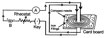
The magnetic lines of force form concentric circles near the wire, with their plane perpendicular to the straight conductor and with their centres lying on its axis. If the direction of current in the wire is reversed, the direction of lines of force is also reversed.
On increasing the strength of current in the wire, the lines of force becomes denser and iron filings are arranged in circles upto a larger distance from the wire, showing that the magnetic field strength has increased.
MAGNITUDE (B) OF MAGNETIC FIELD
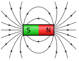
1. If the current (I) in the conductor XY is increased, the deflection of the needle of the compass (used for mapping the field) also increased. Since deflection of the compass is a measure of B, it is clear that magnetic field (B), increases with the increase in current (I), i.e.,
B ∝ I ... (i)
2. If the distance (r) of the compass from the conductor is increased, the deflection of the needle decreases, i.e.,
B ∝ I/r ... (ii)
3. Combing (i) and (ii), we get
B ∝ I/r ... (iii)
Then,
B = μ0 I/2πr
B = Magnetic field strength , μ 0 = Permeability of vacuum (a constant)
I = Current (flowing in conductor) and
r = Distance from the conductor (where magnetic field is measured).
Unit of magnetic field
When current (I) is measured in ampere (A) and distance (r) in metre (m), magnetic field (B) is expressed in a unit named tesla (T).
Direction of magnetic field :
The direction of magnetic field (lines of force) produced due to flow of current can be known by the following rules:
Maxwell's cork screw rule :
Imagine a right handed cork screw lying with its axis coincides with the current carrying wire. It is now rotated such that it advances in the direction of the current, the direction in which the screw rotates gives the direction of the magnetic lines of force.
Direction of current
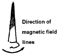
Maxwell's cork screw rule
Right hand thumb rule:
If we hold the current carrying conductor in the right hand such that the thumb points in the direction of current, the fingers encircle the wire in the direction of magnetic lines of force.
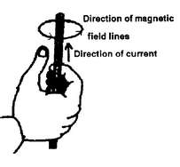
Right hand thumb rule
Magnetic Field due to Circular Coil Carrying Current :
A piece of wire bent in the form of a ring (or coil) is passed through a horizontal cardboard C at two points P and Q at the opposite ends of a diameter of the ring and then some iron filings are scattered on the cardboard. The ends of the coil are connected to a battery through a rheostat and a key. When a strong electric current is passed through the coil by closing the key and the cardboard is gently tapped we find that the iron filings arrange themselves in a definite pattern representing the magnetic lines of force due to the current carrying coil.
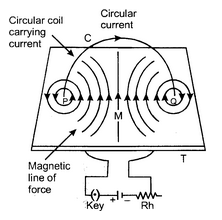
Direction of magnetic field is found by applying the right hand thumb rule to each section of the coil and we find that the concentric lines of force pass through the coil in the same direction. Further note that:
- The magnetic lines of force are nearly circular near the wire.
- Within the space enclosed by the wire, the lines of force are in the same direction.
- Near the centre of the coil, the lines of force are nearly parallel and the magnetic field may be assumed to be practically uniform for a small space around the centre.
- At the centre, the lines of force are along its axis and at right angle to the plane of the coil.
- The magnetic field strength is increased if the number of turns in the coil are increased or the strength of current in the coil is increased.
Since the magnetic lines of force through the coil point in the same direction, hence one face of the coil acts as a large area of north polarity because it is sending out magnetic lines of force and the other face acts as a large area of south polarity as magnetic lines of force are entering it. Thus, the coil has a magnetic field similar to a magnetised iron disc of same radius as that of the coil.
The polarity of the faces of the coil depends on the direction of current and is determined by the clock rule. Looking at the face of the coil, if the current around that face is in an anticlockwise direction, the face has north polartiy while if the current at that face is in the clockwise direction, the face has south polarity. This can be tested by using a compass needle.

(a) Anticlockwise Current (b) Clockwise Current
Magnitude (B) of magnetic field
The magnitude of the magnetic field (B) at the centre of the coil is
1. Directly proportional to the current (I) flowing through it, i.e.,
B ∝ I ... (i)
2. Inversely proportional to the radius (r) of the coil, i.e.,
B ∝ I/r ... (ii)
3. Directly proportional to the total number of turns (N) in the coil, i.e.,
B ∝ N ... (iii)
This is due to the reason that the current in all the circular turns of the coil is in the same direction. As such, the resultant magnetic field due to the coil is equal to the sum of the fields due to all these turns.
Combining (i), (ii) and (iii), we obtain
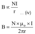
Magnetic field produced by a circular coil carrying current is directly proportional to both, number of turns (N) and current (I), but inversely proportional to its radius (r). Thus, the strength of magnetic field produced by a current carrying circular coil can be increased by
- increasing the number of turns of wire in the coil,
- increasing the current flowing through the coil and
- decreasing the radius of the coil.
MAGNETIC FIELD DUE TO A CURRENT-CARRYING SOLENOID
An insulated copper wire wound on a cylindrical cardboard (or plastic) tube such that its length is greater than its diameter is called a solenoid. The solenoid is from Greek word for “channel”.
To obtain the pattern of magnetic field due to a solenoid, cut a slit in a hard cardboard in such a way that the length of the slit is equal to the length of the solenoid and the width of the slit is equal to the diameter of the solenoid. Fix the solenoid (AB) in the slit in such a manner that the axis of the solenoid is in the plane of the cardboard. The ends of the solenoid are connected to a battery through a rheostat (Rh) and a key (K). Sprinkle iron filings on the board after passing current through the solenoid. On tapping the board, the iron filings arrange themselves in the pattern similar to one shown in figure. The magnetic field lines can also be mapped with the help of a compass needle. The arrows on the field lines are marked in the direction in which the North Pole of the compass needle points, as shown in the figure.
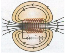
Solenoid
Conclusions:
- The magnetic field lines inside the solenoid are nearly straight and parallel to its axis. Thus, the magnetic field inside a solenoid is uniform.
- The magnetic field lines are exactly identical to those due to a cylindrical bar magnet with one end of the solenoid acting as a South Pole and its other end acting as a North-Pole. Thus, a current-carrying solenoid behaves like a bar magnet with fixed polarities at its ends.
As a result of this:
- A current-carrying solenoid, when freely suspended, sets itself in the North South direction exactly in the same manner as a bar magnet does i.e. it acquires the directive property of a bar magnet.
- A current-carrying solenoid acquires the attractive property of a bar magnet. As such, iron filings are attracted to it when these are brought near it.
Direction of Magnetic Field:
The end of the current-carrying solenoid at which the current flows anticlockwise behaves as a North Pole while that end at which the direction of current is clockwise behaves as a South Pole as shown in figure. This is according to the clock rule, which has earlier been stated.
Magnitude of magnetic field (B)
The magnitude of the magnetic field inside the solenoidis
(i) Directly proportional to the current (I) flowing through the solenoid, i.e.,
B ∝ I ... (i)
(ii) Directly proportional to the number of turns per unit length of the solenoid (n) and not on the total number of turns on the solenoid, i.e.
B ∝ n ... (ii)
Combining (i) and (ii),
B ∝ nI ... (iii)
or