

With the CBSE Class 12 Physics board exam scheduled on 20 February 2026, mastering the Alternating Current (AC) chapter is crucial for scoring high marks. Many students struggle with concepts like AC voltage and current, RMS values, reactance, impedance, and resonance. As this chapter includes both theory and numericals, strong conceptual understanding and consistent practice can significantly boost performance in the examination.
NCERT Solutions for Class 12 Physics Chapter 7 help students revise these concepts quickly, solve numerical problems accurately, and practice step-by-step methods to gain confidence before the exam.
NCERT Solutions for Class 12 Physics Alternating Current
PAC NCERT Solutions cover all concepts of alternating current, including AC voltage, current, RMS and peak values, inductive and capacitive reactance, power in AC circuits, and resonance.
Alternating Current NCERT Solutions are explained in a step-by-step manner, making it easier for students to apply formulas and solve numerical problems efficiently.
Class 12 Physics Chapter 7 Alternating Current
This section provides detailed NCERT Solutions for Class 12 Physics Chapter 7 Alternating Current. Every key topic for the exam is covered to ensure thorough understanding.
These questions and their solutions were developed by our teachers to help students ace their examinations by providing simple explanations and conceptual clarity.
Class 12 Alternating Current NCERT Solutions are given here:
Question 1. A 100 Ω resistor is connected to a 220 V, 50 Hz ac supply.
(a) What is the rms value of current in the circuit?
(b) What is the net power consumed over a full cycle?
Solution : Resistance of the resistor, R = 100 Ω Supply voltage, V = 220 V Frequency, ν = 50 Hz (a) The rms value of current in the circuit is given as: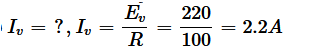 (b) The net power consumed over a full cycle is given as: P = VI = 220 × 2.2 = 484 W
Question 2. (a) The peak voltage of an ac supply is 300 V. What is the rms voltage?
(b) The rms value of current in an ac circuit is 10 A. What is the peak current?
Solution : (a) Peak voltage of the ac supply, V0 = 300 V Rms voltage is given as: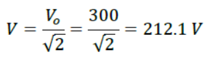
(b) Therms value of current is given as: I = 10 A Now, peak current is given as: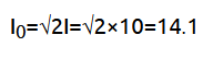
Question 3. A 44 mH inductor is connected to 220 V, 50 Hz ac supply. Determine the rms value of the current in the circuit.
Solution : As given : Inductance of inductor, L = 44 m H = 44 × 10 – 3 H Voltage of source , V = 220 V Frequency of source , ν = 50 Hz Angular frequency of source , ω = 2 π ν à Inductive reactance, X L = ω L = 2 π ν L = 2π × 50 × 44 × 10 – 3 Ω We know that : Rms value of current : à I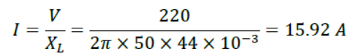
Hence, the rms value of current in the circuit is 15.92 A.
Question 4. A 60 μF capacitor is connected to a 110 V, 60 Hz ac supply. Determine the rms value of the current in the circuit.
Solution : Capacitance of capacitor, C = 60 μF = 60 × 10−6 F Supply voltage, V = 110 V Frequency, ν = 60 Hz Angular frequency, ω=![]() Capacitive reactance
Capacitive reactance![]()
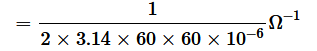
Rms value of current is given as:![]() Hence, the rms value of current is 2.49 A.
Hence, the rms value of current is 2.49 A.
Question 5. In Exercises 7.3 and 7.4, what is the net power absorbed by each circuit over a complete cycle. Explain your answer.
Solution : Given that : Inductive network In the above circuit we have : rms current value, I = 15.92 A rms voltage value, V = 220 V Therefore, the total power taken in can be derived by the following equation : à P = VI cos Φ Here , Φ = Phase difference between V and I. We know that, the difference in phase of alternating voltage and alternating current is 90° , in case of a pure inductive circuit i.e., Φ = 90°.
Therefore, P = 0 i.e., the total power is zero. In case of the capacitive network, The value of rms current is given by , I = 2.49 A The value of rms voltage is given by , V = 110 V Thus , the total power taken in can be derived from the following equation : à P = VI Cos Φ For a pure capacitive circuit, the phase difference between alternating Voltage and alternating current is 90° i.e., Φ = 90°. Thus , P = 0 i.e., the net power is zero.
Question 6. A charged 30 μF capacitor is connected to a 27 mH inductor. What is the angular frequency of free oscillations of the circuit?
Solution : Capacitance, C = 30μF = 30×10−6F Inductance, L = 27 mH = 27 × 10−3 H Angular frequency is given as: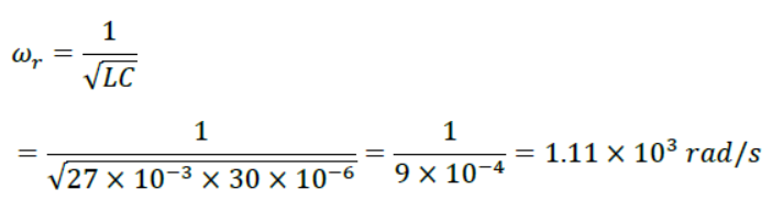 Hence, the angular frequency of free oscillations of the circuit is 1.11 × 10³ rad/s.
Question 7. A series LCR circuit with R = 20 Ω, L = 1.5 H and C = 35 μF is connected to a variable-frequency 200 V ac supply. When the frequency of the supply equals the natural frequency of the circuit, what is the average power transferred to the circuit in one complete cycle?
Solution : At resonance, the frequency of the supply power equals the natural frequency of the given LCR circuit. Resistance, R = 20 Ω Inductance, L = 1.5 H Capacitance, C = 35 μF = 30 × 10−6 F AC supply voltage to the LCR circuit, V = 200 V Impedance of the circuit is given by the relation,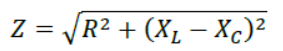
At resonance,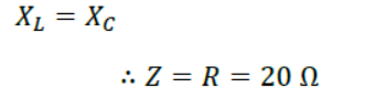
Current in the circuit can be calculated as: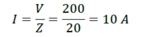
Hence, the average power transferred to the circuit in one complete cycle= VI = 200 × 10 = 2000 W.
Question 8. Figure 7.21 shows a series LCR circuit connected to a variable frequency 230 V source. L = 5.0 H, C = 80μF, R = 40 Ω
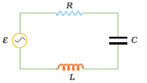
(a) Determine the source frequency which drives the circuit in resonance.
(b) Obtain the impedance of the circuit and the amplitude of current at the resonating frequency.
(c) Determine the rms potential drops across the three elements of the circuit. Show that the potential drop across the LC combination is zero at the resonating frequency.
Solution : Inductance of the inductor, L = 5.0 H Capacitance of the capacitor, C = 80 μF = 80 × 10−6 F Resistance of the resistor, R = 40 Ω Potential of the variable voltage source, V = 230 V (a) Resonance angular frequency is given as: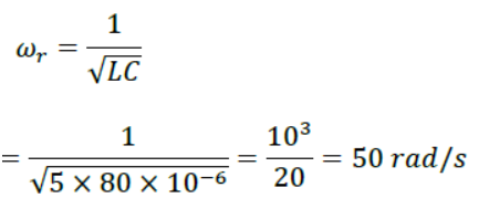
Hence, the circuit will come in resonance for a source frequency of 50 rad/s.
(b) Impedance of the circuit is given by the relation,![]()
At resonance,![]()
Amplitude of the current at the resonating frequency is given as: Where, V0 = Peak voltage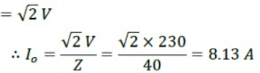
Hence, at resonance, the impedance of the circuit is 40 Ω and the amplitude of the current is 8.13 A.
(c) Rms potential drop across the inductor, (VL)rms = I × ωRL Where, I = rms current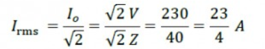
Potential drop across the capacitor,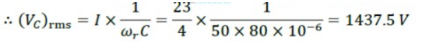 Potential drop across the resistor, (VR)rms = IR =
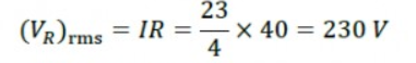
Potential drop across the LC combination, At resonance, ∴VLC= 0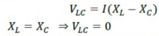
Hence, it is proved that the potential drop across the LC combination is zero at resonating frequency.
Last-Minute Scoring Tips for CBSE Class 12 Physics
With the CBSE Class 12 Physics exam on 20 February 2026, smart revision can make a big difference. Focus on key formulas, important diagrams, and frequently asked concepts to maximize your score. Check below for last-minute scoring tips to boost confidence and performance.
-
Revise all formulas and key derivations thoroughly
-
Focus on numericals that frequently appear in CBSE exams
-
Practice previous year questions and NCERT examples
-
Draw diagrams accurately for full marks
-
Solve one full chapter sample paper before the exam to build confidence