CBSE Class 12 Physics Notes Chapter 6 Electromagnetic Induction
CBSE Class 12 Physics Notes Chapter 6 Electromagnetic Induction is essential for quick revision before the exam tomorrow, 20 February 2026. This chapter explains how changing magnetic fields induce electric currents, covering important concepts like Faraday’s law, Lenz’s law, self-induction, mutual induction, and eddy currents. The notes also include key derivations and practical applications, making it easier to understand complex ideas, revise important points quickly, and boost your confidence for the exam.
CBSE Class 12 Physics Notes Chapter 6 PDF Download
Here we have provided CBSE Class 12 Physics Notes Chapter 6 Electromagnetic Induction PDF for the ease of students so that they can prepare better for their exams by downloading the PDF easily and using it without any internet.CBSE Class 12 Physics Notes Chapter 6 Electromagnetic Induction PDF
CBSE Class 12 Physics Notes Chapter 6 Electromagnetic Induction
Here we have provided CBSE Class 12 Physics Notes Chapter 6 Electromagnetic Induction-Magnetic Flux
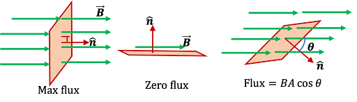 As per the Class 12 Physics Chapter 6 Notes, magnetic flux in any area equals the total number of magnetic field lines of force passing through that area. Net flux through an area A having, under the magnetic influence of B, can be given as Magnetic flux = ɸ = B. dA = BAcosΘ Where, B = magnetic flux through an area A = area under consideration = angle between area vector and magnetic field vector.
- Case 1:
- Case 2:
- Magnetic flux is denoted by ɸ.
- Flux is a scalar quantity.
- The SI unit of magnetic flux is Weber (Wb).
- The CGS unit of magnetic flux is maxwell or gauss.
- 1 Wb = 108 gauss.
- The dimensional formula of flux is [ ɸ ] = [M L2 T-2 A-2].
Electromagnetic Induction
 Electromagnetic induction is a process where a changing magnetic flux in a closed loop induces an electromotive force (emf). When a current flowing through a coil changes, it alters the magnetic field around it, which in turn induces an emf in the coil or in nearby conductors. This induced emf leads to the generation of an induced current if the circuit is closed. The phenomenon is fundamental to many technologies, including transformers, electric generators, and inductors.
Faraday’s Law of EMI:
There are two laws under Faraday’s Law of EMI.- Law 1:
- Law 2:
- By changing/ adjusting magnetic field B.
- By changing the area under consideration, A.
- By changing the angle .
Lenz’s Law
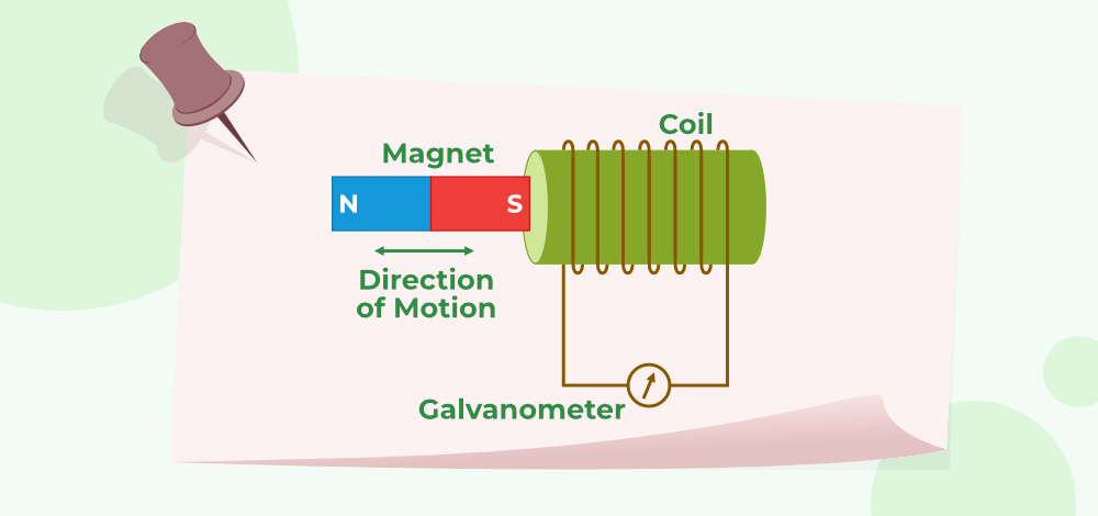
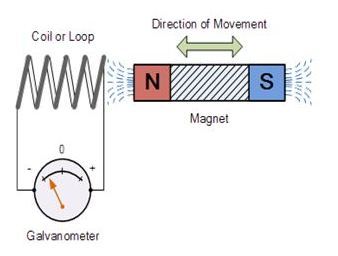
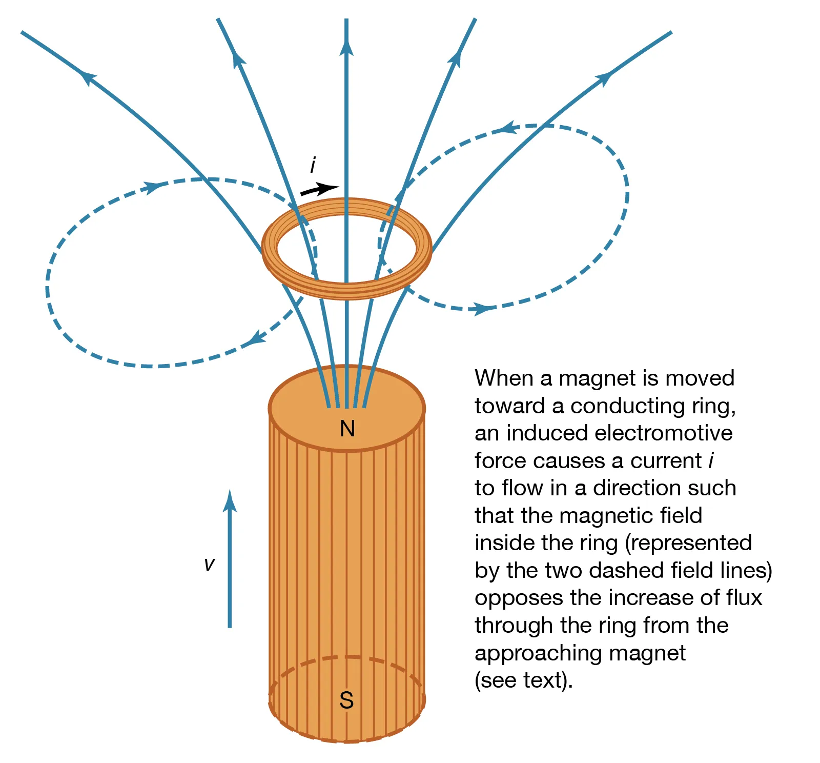 Lenz’s Law states that the direction of the induced emf or current in a circuit always opposes the change in magnetic flux that caused it This law is rooted in the principle of conservation of energy. For a better understanding, let's consider how the magnetic field and force change depending on the position of the magnet relative to the coil:
| Position of Magnet | Direction of Induced Current | Behavior of Coil’s Face | Type of Magnetic Force | Magnetic Field Linked with Coil |
|---|---|---|---|---|
| Towards the coil | Anticlockwise | North pole | Repulsive force | Increases |
| Away from the coil | Clockwise | South pole | Attractive force | Decreases |
| Towards the coil | Clockwise | South pole | Repulsive force | Increases |
| Away from the coil | Anticlockwise | North pole | Attractive force | Decreases |
Eddy Current
Eddy currents are loops of electric current induced within conductors when there is a change in magnetic flux. These currents are formed in a large piece of conductor and have significant magnitudes, often generating considerable heat due to the low resistance of the material. According to Lenz's law of electromagnetic induction, these currents swirl in a manner that creates a magnetic field opposing the change in flux, resulting in energy loss primarily in the form of heat.Properties of Eddy Currents:
- Eddy currents are similar to water eddies, circulating in closed loops within the conductor.
- Also known as "Foucault currents," named after the scientist who first proposed their experimental hypothesis.
- The generation of eddy currents leads to electrical energy loss as heat, often considered undesirable in many applications.
Applications of Eddy Currents: While energy loss due to eddy currents is usually minimized, in some cases, this effect is harnessed for specific applications:
- Braking Systems: In trains, roller coasters, and certain power tools like electric saws and drills, eddy currents are used to provide braking force. The magnetic interaction with the metal wheels slows down the vehicle smoothly.
- Induction Furnaces: Eddy currents generate heat in metals, aiding in processes like melting and alloy formation.
- Induction Cooking: Eddy currents are also utilized in induction cooking, where they heat the cookware directly.
- Adjustable Speed Drives: Eddy currents, controlled by a feedback system, help in achieving adjustable speed drives in various machinery.
Induced Charge Flow
When a changing magnetic flux induces a current in a circuit, a charge flows through the circuit as a result. The total charge that flows through the circuit, due to this induced current, can be calculated by integrating the current over the time interval during which the flux is changing. This net charge Q flowing through the circuit can be expressed as: q = i dt = 1/R dɸ/dt dt = 1/R dɸ q = Δɸ / R and q = N Δɸ / R where N = number of turnsInduced Electric Field
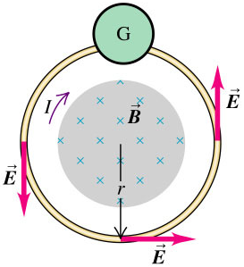 In Class 12 Physics Chapter 6, it is explained that the induced electric field is non-conservative and non-electrostatic. Unlike electrostatic fields, the electric field generated by a changing magnetic field does not have a potential function and cannot be described simply by a gradient of a scalar potential. Instead, the field lines form concentric circles and create closed loops around the region where the magnetic flux is changing.
Motional EMF in a Loop by Generated Area
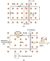 When a conducting rod moves through a magnetic field, it generates an electromotive force (EMF) in a loop formed by the rod and two parallel conducting rails. This phenomenon is utilized to understand how motional EMF is induced due to the movement of a conductor in a magnetic field. Here’s how it works:
- Setup: Imagine a setup with two parallel conducting rails and a conducting rod that slides along these rails. The rails are connected to form a closed loop with the rod.
- Movement: As the rod moves through the magnetic field, it sweeps out an area between the rails. This area changes as the rod moves, causing a change in the magnetic flux through the loop.
Periodic EMI
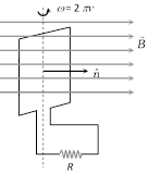 When a rectangular coil with N turns rotates in a uniform magnetic field, an electromotive force (EMF) is periodically induced in the coil due to the changing magnetic flux. Here’s a breakdown of the process: Having ⍵ its angular speed, v = frequency of coil’s rotation, R = resistance of the coil Hence, a flux is linked to the coil due to uniform rotational motion, which is given as, ɸ = NBA cosΘ = NBA cos⍵t ɸ = ɸocos⍵t where ɸo = NBA = maximum flux.
Induced EMF
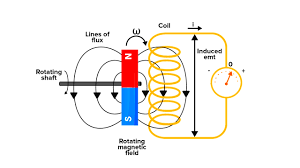 The electromotive force (EMF) induced in a coil or conductor changes in response to variations in magnetic flux. This change can occur in different patterns depending on the nature of the magnetic field and the movement of the coil or conductor. When the EMF changes in a repeating or cyclical pattern, it is referred to as Periodic EMF. This typically happens when the conductor or coil is exposed to a magnetic field that varies periodically with time, such as in the case of a rotating coil in a uniform magnetic field. Periodic EMF occurs due to the continuous change in the magnetic flux linked with the coil, which is a result of its rotational motion or the changing magnetic field. This results in a sinusoidal variation of the induced EMF over time, which can be mathematically described using Faraday’s Law of Electromagnetic Induction. The EMF varies in a regular, predictable pattern, making it periodic. Induced emf is given as, e = dɸ/dt = NBA⍵ sin⍵t E = eo sin⍵t where eo = maximum emf = NBA⍵ = ɸo⍵
Induced current
 At any time t, the induced current i is given as, i = e/R = eo/R sin⍵t = io sin⍵t Where io = maximum current or current amplitude
Inductance
Inductance is a fundamental property of electrical circuits that opposes changes in current. When the current through a coil changes, it alters the magnetic flux around the coil. According to Faraday’s Law of Electromagnetic Induction, this changing flux induces an electromotive force (EMF) in the coil that opposes the change in current. This process is known as self-induction, and the induced EMF is often referred to as back-EMF. Inductance measures how much a coil or circuit resists changes in current. A higher inductance means greater opposition to current changes. For a straight wire carrying current without any iron core, the inductance is relatively low compared to a coil with an iron core, which significantly enhances the inductance. Understanding inductance can be challenging for many students. To grasp these concepts more effectively students are encouraged to refer to our Class 12 Physics Chapter 6 Notes where our subject experts break down these complex ideas into simpler more understandable explanations. Self-inductance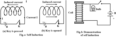 Self-inductance is a phenomenon where an emf is induced by changing the current in the coil. Some important Properties:
- L deNotes the inductance of self-inductance.
- The SI unit of inductance is Henry and denoted by H.
- The dimensional formula of inductance is [ M L2 T-2 A-2 ].
- Coefficient of self induction = L = Nɸ /i.
- Self inductance for circular coil is = L = µoN2A /2R.
- Self-inductance of a solenoid = L = µoN2A /l.
- Self-inductance for a square coil is L = 2√2 µoN2a / π.
- Energy stored in an inductor = 12LI².
- Self-inductance or L does not depend on the current flowing through the coil/conductor.
- Instead, L depends on the number of turns or N, area of cross-section A, and permeability of medium µ.
- Moreover, self-inductance or L only begins to show whenever there is a change in current.
Preparation Strategy for CBSE Class 12 Physics Notes Chapter 6 Electromagnetic Induction
To score well in the exam tomorrow, 20 February 2026, follow this focused preparation strategy for effective last-minute revision:
Understand the Central Concepts: Focus on the main ideas such as electromagnetic induction, Faraday’s law, Lenz’s law, self-induction, mutual induction, and eddy currents. A clear understanding of these concepts is crucial for both theory and numerical questions.
Revise Key Derivations: Go through important derivations like the expression for induced emf, self-inductance, and mutual inductance. Understanding the steps helps you answer numerical and conceptual questions quickly.
Practice Numerical Problems: Solve a few significant numerical problems involving induced emf, current, and inductance to strengthen problem-solving speed and accuracy.
Review Diagrams and Examples: Quickly revise diagrams like coils, solenoids, and setups for Faraday’s and Lenz’s law. Examples in the notes illustrate applications and help answer long-answer questions effectively.
Use Notes for Quick Revision: Go through CBSE Class 12 Physics Notes Chapter 6 Electromagnetic Induction for last-minute preparation. Focus on highlighted points, formulas, and practical examples to clear doubts efficiently.
CBSE Class 12 Physics Notes Chapter 6 Electromagnetic Induction FAQs
What is electromagnetic induction?
What is Faraday's Law of Electromagnetic Induction?
What is Lenz's Law?
What are eddy currents?
What is self-induction?