Kirchhoff Law
Share
Kirchhoff Law
Current Electricity of Class 12
KIRCHHOFF LAW :
There are certain rules and techniques to solve the complicated circuits, containing resistances and batteries. These rules enable us to handle the complicated circuit systematically. The method given by Kirchoff is one of them. Kirchoff’s law is incomplete without defining the basic terms.
Branch Point
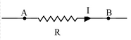
The branch point in the network is the point where three or more conductors are joined.
Loop
A loop is any closed conducting path.
Junction rule
It is based on the law of conservation of charge. At a junction in a circuit, the total incoming current is equal to the total outgoing current. In other words, the algebraic sum of the currents at a junction is zero. A junction in a circuit is neither acts as a sink nor as a source of charge.
Loop rule
It is based on the law of conservation of energy. The algebraic sum of the potential drop around any closed path is zero.
|
|
-
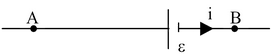
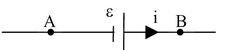
For an emf source, the changes in potential will be obtained as illustrated below.
|
Emf = ε, internal resistance = r
vB – vA = − ε − ir |
Emf = r ε, internal resistance = r
vB − vA = ε − ir |
|
Illustration16. Calculate current in each resistance in the electrical circuit shown in the figure. The internal resistances of the cells are negligible. |
|
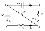
Solution: Applying Kirchhoff’s second law to the mesh adca, we get
− I1 × 1 – 2 (I1 + I2) + 1 = 0
I1 + 2(I1 + I2) = 1
3I1 + 2I2 = 1. . . (i)
Applying Kirchhoff’s second law to the mesh abca, we get
2 – 1 × I2 – 2(I1 + I2) = 0
or, I2 + 2(I1 + I2) = 2
2I1 + 3I2 = 2 . . . (ii)
solving (i) and (ii), we get,
I1 = − 0.2 A and I2 = 0.8 A
Current in 2Ω resistance = (0.8 – 0.2)A = 0.6 A.
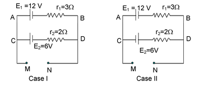
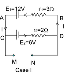
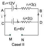
Illustration 17. What is the potential difference between the points M and N for the circuits shown in the figures, For case I and case II?
|
Solution : Case I:
I =
= 12 − 1.2 × 3 = 8.4 V For cell E2, vC − E2 − Ir2 = vD i.e. vC − vD = 6 + 1.2 x 2 = 8.4 V |
|
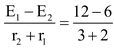 = 1.2 A So for cell E1, vA − E1 + Ir1 = vB i .e. vA − vB = E1 − Ir1
Hence, vC − vD = vA − vB = vM − vN = 8.4 V
|
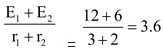
Case II: I =
vA − E1 + Ir1 = vB i.e. vA − vB = E1 − Ir1 = 12 – 3.6 ×3 = 1.2 V For cell E2, vc + E2 − Ir2 = vD i.e. vC − vD = −E2 + Ir2 = −6 + 3.6 × 2 = 1.2 V Hence, vA − vB = vC − vD = vM − vN = 1.2 V |
|
|||
|
Illustration 18. The given network is part of another larger circuit. Calculate the potential of point D. |
|
|||
 A For cell E1,
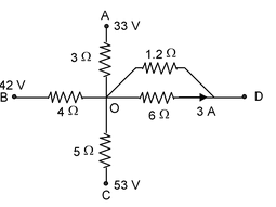
Solution : Let the potential of point O be x volts
Going from D to O, we get VO − VD = 6 × 3 = 18 volt
⇒ VD = x – 18
Let us assume that the current goes away from point O to the points A, B, C and D through all branches
⇒ iOA + iOB + iOC + iOD = 0
⇒
⇒
 ⇒ x = 18 V
⇒ D is at a potential of 0 volts.
Illustration 19. The following figure shows part of certain circuit. Find
(i) power dissipated in 6 Ω resistance.
(ii) potential difference VC − VB
(iii) potential difference VA − VD
|
|
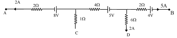
Solution:
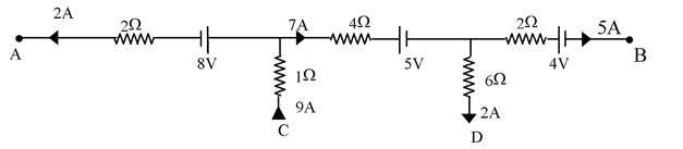
Apply junction rule to calculate the current through each resistor
(i) P = I2R ⇒ P(6Ω) = 24 watt
(ii) VC − VB = VBC = 4 + (5 × 2) + 5 + (7 × 4) + 9 × 1 = 55 V
(iii) VA − VD = VDA = −2 × 2 − 8 + 7 ×4 + 5 + 6 × 2 = 33 V
|
Illustration 20. Find the equivalent resistance between M and N. |
|
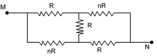
|
Solution : For loop 1: −I1R + R(I – 2I1) + nR(I – I1) = 0 ⇒ I1 (R + 2R + nR) = I (R + nR) ⇒ I1 = I(n + 1)/(n + 3) For loop AMCNDA ; we have from Kirchoff’s loop law −I1R – (I – I1)nR + V = 0 ⇒ I1 (R – nR) = V – nIR ⇒ I(n + 1)/(n + 3) R(1 – n) + nIR = V |
|
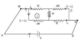
⇒ IR
 = V
= V
⇒ V = IR (1 + 3n)/(n + 3)
∴ Req = (3n + 1)/(n + 3)R
Carbon Resistors
To make a carbon resistor, carbon with a suitable binding agent is moulded into a cylinder. Wire leads are attached to this cylinder. The resistor is enclosed in a plastic or ceramic jacket. The resistor is connected to the circuit by means of two leads. Carbon resistors of different values are commercially available. They are widely used in electronic circuits of radio, amplifier, etc.
Colour Code for Carbon Resistors
The resistances of a carbon resistor are indicated by means of colour code printed on it. The resistor has a set of coaxial coloured rings on it with their significance as indicated in the table shown.
|
Colour |
Number |
Multiplier |
Tolerance (%) |
|
Black |
0 |
1 |
|
|
Brown |
1 |
101 |
|
|
Red |
2 |
102 |
|
|
Orange |
3 |
103 |
|
|
Yellow |
4 |
104 |
|
|
Green |
5 |
105 |
|
|
Blue |
6 |
106 |
|
|
Violet |
7 |
107 |
|
|
Gray |
8 |
108 |
|
|
White |
9 |
109 |
|
|
Gold |
10−1 |
5 |
|
|
Silver |
10−2 |
10 |
|
|
No colour |
20 |
To read the value of a carbon resistance, the following sentence serves as an aid to memory.
BBROY Great Britain very good wife
From the left end, first two bands indicate the first two significant figures of the resistance in ohms. The third band indicates the decimal multiplier and the last band indicates the tolerance or possible variation in percent about the indicated value. In the absence of fourth band, tolerance is ± 20%.
|
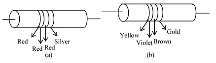
Illustration 21 .The figure shows a colour–coded resistor. What is the resistance of this resistor? |
|
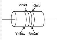
Solution: The number for yellow colour is 4. The number for violet colour is 7. Brown colour gives a multiplier of 101. Gold indicates a tolerance of 5%. So, the resistance of the given resistor is 47 × 10 Ω ± 5%.