Alternating Current
Electromagnetic Induction of Class 12
Alternating Current
A current which flows first in one direction in a circuit, called the positive direction, then in the reverse direction or negative direction is called alternating current. This cycle shown in figure is repeated again and again and has an average value of zero over a period. Since the variation of the current strength is sine wave as shown in figure, the value of current at any instant say t seconds after it had zero value will be given by the following expression:
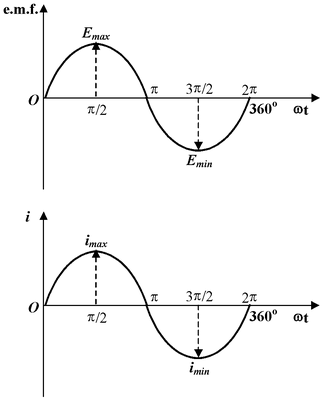
i = Imax sinωt
where i is the value of current at time t and Imax is the maximum value of the current and ω is the angular frequency ( = 2πf, f being frequency).
Both the emf and current undergo a complete cycle of changes, having positive and negative value, every time ωt changes by 360o or 2π radians as shown in figure.
Different Forms of a.c. emf
The variation of A.C. quantity is sinusoidal hence can be expressed as:
e = Emax sin ωt as ω = 2πf, we have
e = Emax sin(2πft) since f = 1/T, we have
e = Emax sin (2πt/T)
Phase of An A. C. Quantity
Phase of an A. C. quantity represents the fraction of the time period of that alternating quantity that has elapsed since the current last passed through the zero position of reference. Phase is also expressed in terms of angle in radians. For example phase at A is T/4 second or π/2 radians. In electricity we are more concerned with the phase difference rather than absolute phase of an alternating quantity. Phase difference between quantities indicates the lag or lead of an alternating quantity with respect to other.
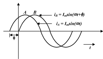
A leading quantity is the quantity which reaches maximum (or zero) value earlier as compared to the other quantity, while lagging alternating quantity is one which reaches its zero or maximum value later than the other quantity. In figure two alternating quantities are shown quantity A leads B by an angle φ. Hence their equations are
iA = Imax sin ωt and iB = Imax sin (ωt + φ)
Effective Virtual or R. M. S. value of a Quantity
The r. m. s. (or effective apparent) value of an alternating current is the value of the direct current which produces same amount of heat in the same time in the same conductor. An alternating current is not steady but varies from instant to instant. If i1, i2, i3, …….. in are instantaneous currents r. m. s. value will be
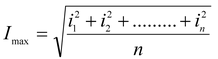
we can also expresses this value as
Ir.m.s. = Imax/√2 = 0.707 Vmax
Similarly Vr.m.s. = Vmax/√2 = 0.707 Vmax
Mean or Average Value of an Alternating Quantity
The mean value or average value (Iav) of an alternating current is equal to the steady current which transfers across any circuit the same charge as is transferred by the alternating current during the same time.
In case of sinusoidal or symmetrical alternating current, the average value over complete cycle is zero. Hence in these cases the average value is obtained by integrating the instantaneous values of alternating quantity over half cycle only. The alternating currents average value is given by
Iav = 2Imax/π orIav = 0.637 Imax
Form Factor
The ratio of the root mean square (r.m.s.) to the average value of an alternating current gives an indication of the shape of the wave and is known as its form factor and is denoted by K i.e.
Form factor K = 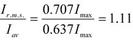
Thus for sine wave form factor is 1.11
A. C. Circuit containing Resistance Only (Resistive Circuit)
In a circuit containing pure resistance (ohmic) only i.e. free from any inductance or capacitance in the circuit, the current and potential difference between any two points is given by i = v/R where i and v are instant current and voltage respectively and R is the resistance between the points. The emf applied is
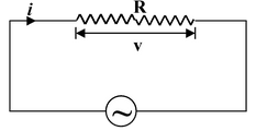
v = Vmax sin ωt
and the current i = vmax/R sin ωt, Imax = Vmax/R
or i = Imax sin ωt
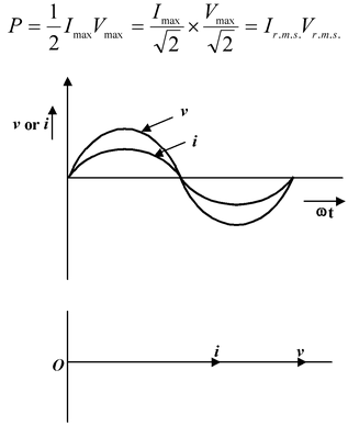
This shows that the current and voltage are in phase. Graphically it is shown in figure (a) and vectorically in figure (b).
The power in a circuit is given by P (= v × i)
hence P = Imax sin ωt × Vmax sin ωt
or P = 1/2 Imax Vmax(1 - cos 2ωt)
The power consists of a constant part ½ Imax Vmax/2 and a variable part ½ ImaxVmax cos 2ωt. The average value of variable part of power over a cycle is zero. Thus the average power for one cycle is
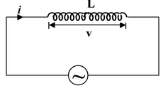
A. C. Circuit Containing Inductor Only (Inductive Circuit)
Consider a circuit having no ohmic resistance and only inductance L as shown in figure. When an A. C. current is passed through this circuit a magnetic flux is set up which induces alternating emf in the inductance which is L(di/dt) and opposes the variation of current through it at every instant. If the applied voltage is vmax sin ωt we have
Ldi/dt = Vmax sin ωt
Integrating above relation we have
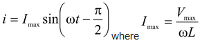
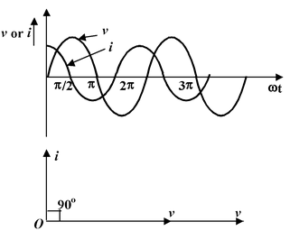
From the above relation it is clear that there is a phase difference of π/2 between voltage and current i.e. current lags voltage by π/2 radians. Graphically, the voltage and current wave are as shown in figure (a) and vectorically as shown in figure (b).
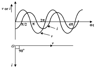
The quantity ωL is called inductive reactance or reactance and denoted by XL (= ωL = 2πfL). The power in an inductive circuit is given by
P = -1/2 Vmax Imaxsin 2ωt
As there is no constant term in power expression, hence the average power in a pure inductive circuit is zero. This is called wattles power.
A. C. Circuit Containing Capacitance Only (Capacitive Circuit)
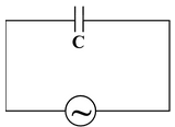
When an alternating voltage is applied to the plates of the capacitor, they are first charged in one direction and then in the opposite direction. If the applied voltage is v = Vmax sin ωt, the potential difference between the plates at any instant will be v = q/c = Vmax sin ωt and the current (dq/dt) is given by
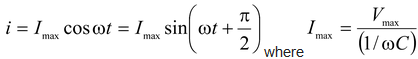
From above relation it is clear that current leads the applied voltage by 90o or π/2. The quantity 1/ωC is called reactance or capacitive reactance and denoted by XC.
The voltage and current waves are as shown in figure (a) and vectorically as shown in figure (b).
The power in the circuit is given by
P = Vmaxsin ωt Imax cos ωt = 1/2 Imax Vmax sin 2ωt
Thus the average power consumed in a pure capacitive circuit is zero.
Resistance and inductance in series A. C. Circuit
In a circuit containing a pure inductance L and a pure resistance R connected in series as shown in figure, when an A. C. voltage is applied in this circuit, the voltage drops on the resistance say vR( = iR in phase with current) and on the L say vL (= ωL), leading the current by 90o. These voltages are shown by the vector diagram in figure.
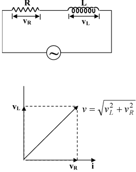
The resultant voltage is given by
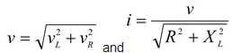
The term  is called impedance of the circuit and denoted by Z (its units are ohm) i.e.
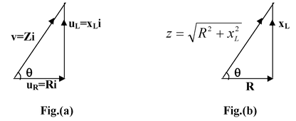
Z =
The triangle whose sides are proportional to the voltages are called voltage triangle (fig.(a)) and a triangle whose sides are proportional to R, XL and Z is called impedance triangle (fig.(b)).
Average power in R and L in series circuit when A. C. current passes is given by
P = Vr.m.s. Ir.m.s. cos φ
where φ is the angle by which vector v leads the vector i. The value of cos φ (=R/Z) is constant for a given circuit and is known as power factor. It is defined as the factor by which product of rms current and voltage should be multiplied to have true power in watt.
If φ is 90o i.e. cos φ = 0, the ohmic resistance of the A. C. current is zero and the average power also remains zero, i.e. inspite of flow of current there is no dissipation of energy. The current in such a circuit is called wattles current. In practice we can not have a resistance free circuit and hence wattles current is not a reality.
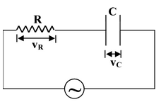
Resistance and Capacitance in Series A. C. Circuit
Such a circuit having resistance, capacitance in series with an A. C. source is shown in figure.