LR Circuits
Electromagnetic Induction of Class 12
LR CIRCUITS
How to apply Kirchhoff's voltage law across an inductor.
Always assume current to be an increasing function with time. The voltage drop or gain may be taken as explained below:
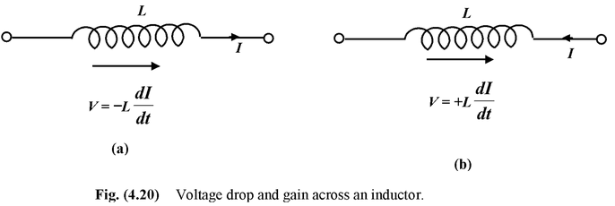
(i) If the direction of current coincides with the direction of motion the voltage across the inductor falls and is given by V = −LdI/dt (see fig.(4.20 a)).
(ii) If the direction of current is opposite to the direction of motion the voltage across the inductor rises and is given by V = + LdI/dt (see fig.(4.20 b)).
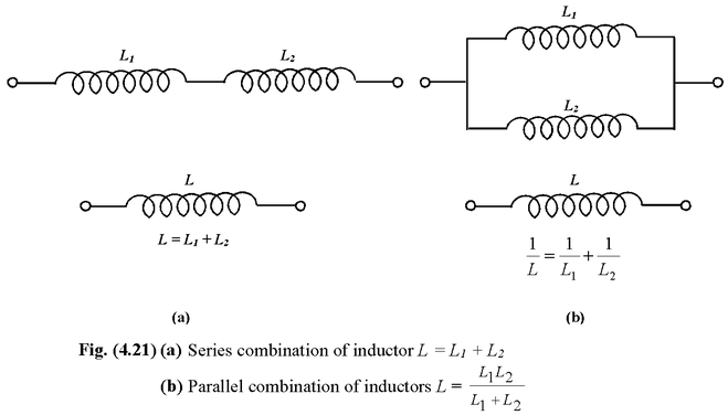
Series and Parallel Combination
If we ignore the mutual induction effect of the coils, then the series and parallel combination of inductors are similar to resistors.
Example: 4.9
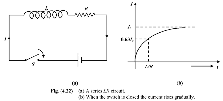
The Fig. 4.22 (a) shows a series LR circuit. When the switch is closed derive an expression for the instantaneous current through the inductor.
Solution
Let I be the instantaneous current through the circuit. Applying Kirchoff's voltage law
E − LdI/dt − IR = 0(i)
On rearranging the equation, we get
 (ii)
(ii)
On integrating both the sides, we get
-ln 
At t = 0, I = 0 ⇒ K = −ln |E/R|
Thus, −ln 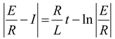 (iii)
(iii)
On rearranging equation (iii) we get
I = 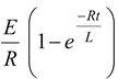
orI = I0 (1 − e-t/τ)(4.14)
where I0 = E/R is the final value of I at t = ∞ and the quantity τ = L/R is called the time constant.
In one time constant the current rises to (1− e-1) I0 = 0.63I0 as shown in Fig. 4.22 (b).
Example: 4.10
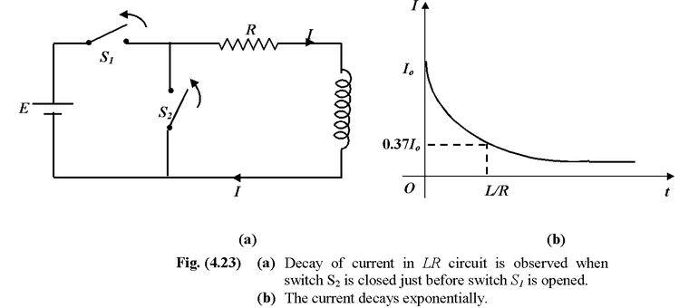
For the circuit shown in the Fig. 4.23 (a) the switch S1 is initially closed and switch S2 is open. The circuit is in the steady state condition. Suddenly the switch S1 is opened and the switch S2 is closed. Derive an expression for the decay of current.
Solution
Let I be the instantaneous current in the circuit as shown in the fig. Applying Kirchoff's voltage law, we get
−IR - L dI/dt = 0
or 
on integrating both the sides.
ln |I| = −
At t = 0, I = I0 = E/R ⇒K= ln|I0|
Thus, ln|I| = 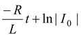
Further simplifying I = I0 e-Rt/L
In this case the time constant τ = L/R is the time at which the current falls to 1/e or 37% of its initial value I0, as shown in the Fig. 4.23(b).